Continuous conductivity and temperature monitoring
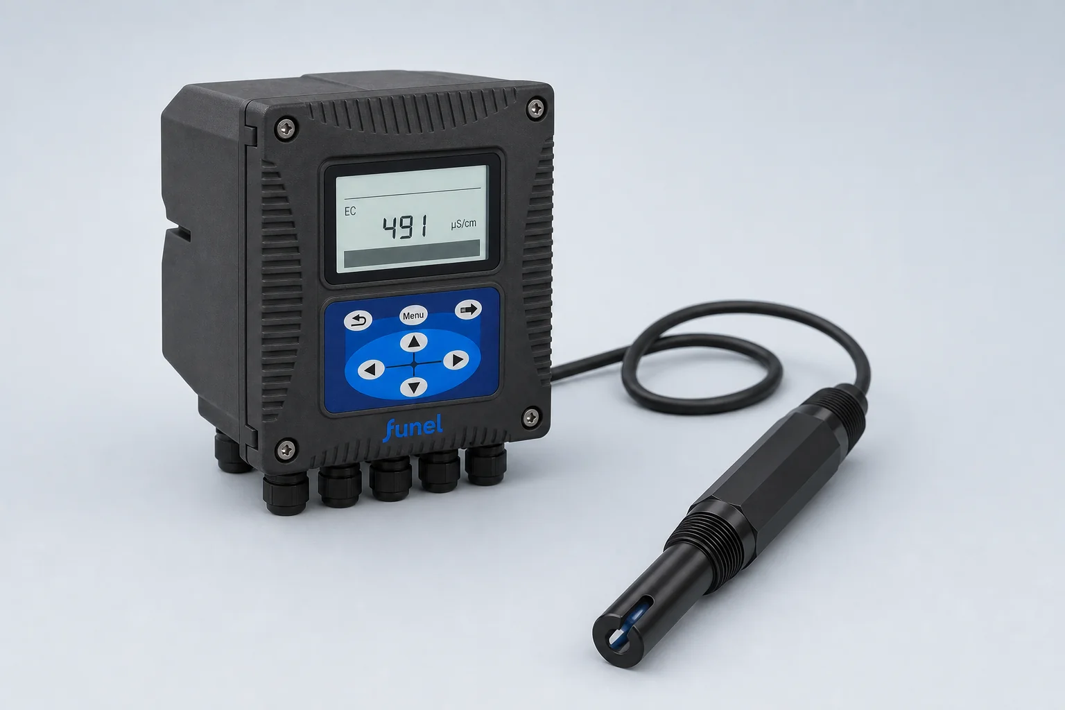
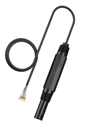
Online system · Configured online system
Online Conductivity Analyzer
A configured sensor-and-controller system for continuous conductivity and temperature monitoring in water treatment and industrial processes.
10–5000 µS/cm3 × 4–20 mAModbus RS485
Structured from the supplied technical files
Only values confirmed in the current records are published. Products without a commercial model remain configured products; final range, cell constant, material, interface and accessories are controlled by the project datasheet.
01
Construction and product highlights
Automatic temperature compensation
Three 4–20 mA outputs
Three configurable relays
Modbus RS485 communication
Wall, panel or pipe mounting for the controller
02
Product technical specifications
The source file does not provide a dedicated commercial model number. Final sensor, controller power, outputs, mounting and cable are confirmed as a project configuration.
- Measuring range
- Conductivity: 10–5000 µS/cm; temperature: 0–80°C
- Accuracy / linear error
- Conductivity: ±1% or ±1 µS/cm, whichever is greater; temperature: ±0.5°C
- Pressure
- ≤0.6 MPa
- Response time
- ≤10 s to 95% endpoint after stirring
- Wetted / housing material
- Black polypropylene housing; glass platinum electrode
- Protection
- Sensor IP68 / NEMA6P; controller IP65 / NEMA4X
- Display
- 128 × 64 graphical LCD with LED backlight
- Power
- 85–500 VAC (50/60 Hz) or 9–36 VDC
- Output / communication
- 3 × 4–20 mA; Modbus RS485
- Relays
- 3 configurable relays
- Dimensions
- 145 × 125 × 162 mm; 1.35 kg
03
Recommended applications
Municipal water
Online conductivity trends in water treatment and distribution.
Municipal wastewater
Continuous monitoring across wastewater treatment processes.
Aquaculture
Monitor conductivity changes together with process temperature.
Industrial process water
Integrate conductivity signals with plant control and recording systems.
04
Items to confirm
The source file does not provide a dedicated commercial model number. Final sensor, controller power, outputs, mounting and cable are confirmed as a project configuration.
- 01Minimum, normal and maximum conductivity
- 02Water chemistry, temperature and pressure
- 03Cell constant, wetted material and mounting thread
- 04Cable, power, 4–20 mA or RS485 Modbus
05
Configuration documents
Confirm the sensor, controller, mounting accessories and wiring documents as one package. Related product brochures are available below.
Get a quote- Configured datasheet✓
- Mounting and wiring drawings✓
- Interface and accessory schedule✓
06
Related conductivity products
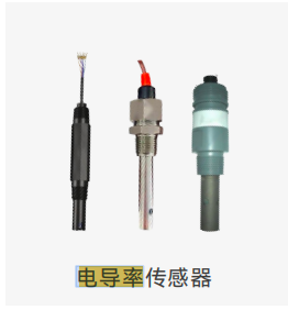
Analog Conductivity Sensor Series
View product↗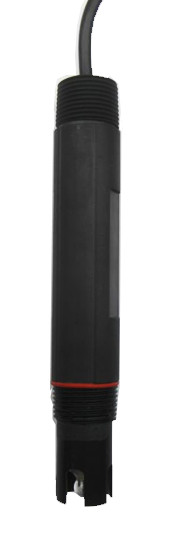
Digital Conductivity Sensors
View product↗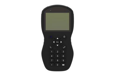
Portable Conductivity Analyzer
View product↗Selection & service
From selection to installation
Choose conductivity measurement by the actual operating range, cell construction and signal path. A complete analyzer and a digital sensor are different supply configurations.
Product literature
Download product brochures
The brochure's PEC-500 on PDF page 2 lists a 10–5,000 µS/cm range and 3% linear error. Other sensor options use different accuracy statements; request the configured datasheet when comparing quotations.
Contact FUNEL
Tell us what you need to measure.
We will respond with a recommended configuration, supporting documentation and quotation.