Direct digital communication
Digital integration · PEC-500B + Digital EC
Digital Conductivity Sensors
Direct RS485 Modbus output supports long-distance integration without treating the analog and digital sensor configurations as the same product.
RS485 ModbusIP68 / NEMA6PUp to 200 m cable
Structured from the supplied technical files
Only values confirmed in the current records are published. Products without a commercial model remain configured products; final range, cell constant, material, interface and accessories are controlled by the project datasheet.
01
Construction and product highlights
Power and communication protection circuits
Long-distance project cabling
Internal storage of calibration and settings on the PPS configuration
IP68 / NEMA6P sensor protection
Two separately verified configurations
02
Product technical specifications
Confirm whether the project requires the PEC-500B 316L construction or the PPS digital configuration, then verify power, range, pressure, temperature and cable.
- Output / communication
- RS485 Modbus / Modbus RTU
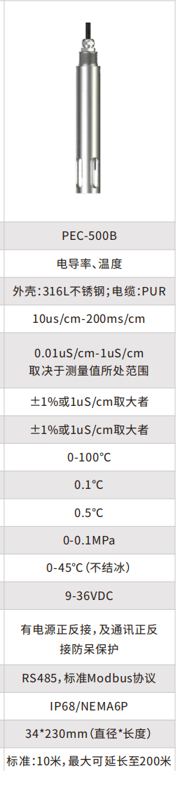
- PEC-500B measured parameters
- Conductivity and temperature
- PEC-500B measuring range
- 10 µS/cm–200 mS/cm
- PEC-500B accuracy / resolution
- Conductivity: ±1% or ±1 µS/cm, whichever is greater; 0.01–1 µS/cm resolution depending on range
- PEC-500B temperature compensation
- 0–100°C; 0.1°C resolution; ±0.5°C accuracy
- PEC-500B pressure
- 0–0.1 MPa
- PEC-500B response time
- <10 s
- PEC-500B power
- 9–36 VDC
- PEC-500B output / communication
- RS485 Modbus
- PEC-500B cable
- 10 m standard; up to 200 m
- Configuration note
- PEC-500B and the PPS digital sensor use different verified specifications and must not be treated as one model.
03
Configuration and model comparison
316L digital conductivity and temperature sensor
10 µS/cm–200 mS/cmRS485 Modbus9–36 VDC
- Measured parameters
- Conductivity and temperature
- Wetted / housing material
- 316L stainless-steel housing; PUR cable
- Measuring range
- 10 µS/cm–200 mS/cm
- Resolution
- 0.01–1 µS/cm depending on the measured range
- Accuracy / linear error
- ±1% or ±1 µS/cm, whichever is greater
- Repeatability
- ±1% or ±1 µS/cm, whichever is greater
- Temperature measurement
- 0–100°C; 0.1°C resolution; ±0.5°C accuracy
- Pressure
- 0–0.1 MPa
- Operating temperature
- 0–45°C, non-freezing
- Power
- 9–36 VDC
- Electrical protection
- Reverse-polarity and surge protection
- Output / communication
- RS485, Modbus
- Protection
- IP68 / NEMA6P
- Dimensions
- Ø34 × 230 mm
- Cable
- 10 m standard; up to 200 m
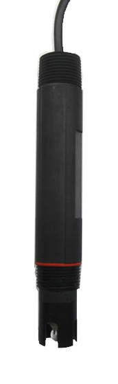
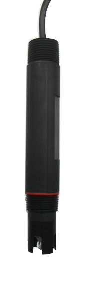
Digital conductivity sensor from the supplied product file
0–20.00 mS/cmRS485 Modbus RTU12 VDC
- Measuring range
- 0–200.0 µS/cm; 0–2000 µS/cm; 0.01–20.00 mS/cm
- Wetted / housing material
- PPS
- Resolution
- 0.1 µS/cm; 1 µS/cm; 0.01 mS/cm
- Accuracy / linear error
- ±2% FS
- Repeatability
- ±1%
- Operating temperature
- 0–60°C, non-freezing
- Pressure
- 0–0.1 MPa
- Power
- 12 VDC
- Output / communication
- RS485, Modbus RTU
- Protection
- IP68 / NEMA6P
- Dimensions
- Ø26 × 166 mm
- Mounting
- 3/4-inch front and rear threads
- Cable
- 10 m standard; up to 200 m
04
Recommended applications
Remote water stations
Use RS485 Modbus for long cable runs and direct automation integration.
Wastewater treatment
Continuous conductivity and temperature trends in treatment processes.
Surface water
Integrate conductivity with other monitoring parameters at remote points.
Industrial networks
Connect digital sensors to PLC, RTU or multiparameter systems after protocol confirmation.
05
Items to confirm
Confirm whether the project requires the PEC-500B 316L construction or the PPS digital configuration, then verify power, range, pressure, temperature and cable.
- 01Minimum, normal and maximum conductivity
- 02Water chemistry, temperature and pressure
- 03Cell constant, wetted material and mounting thread
- 04Cable, power, 4–20 mA or RS485 Modbus
06
Configuration documents
Confirm the sensor, controller, mounting accessories and wiring documents as one package. Related product brochures are available below.
Get a quote- Configured datasheet✓
- Mounting and wiring drawings✓
- Interface and accessory schedule✓
07
Related conductivity products
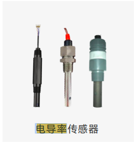
Analog Conductivity Sensor Series
View product↗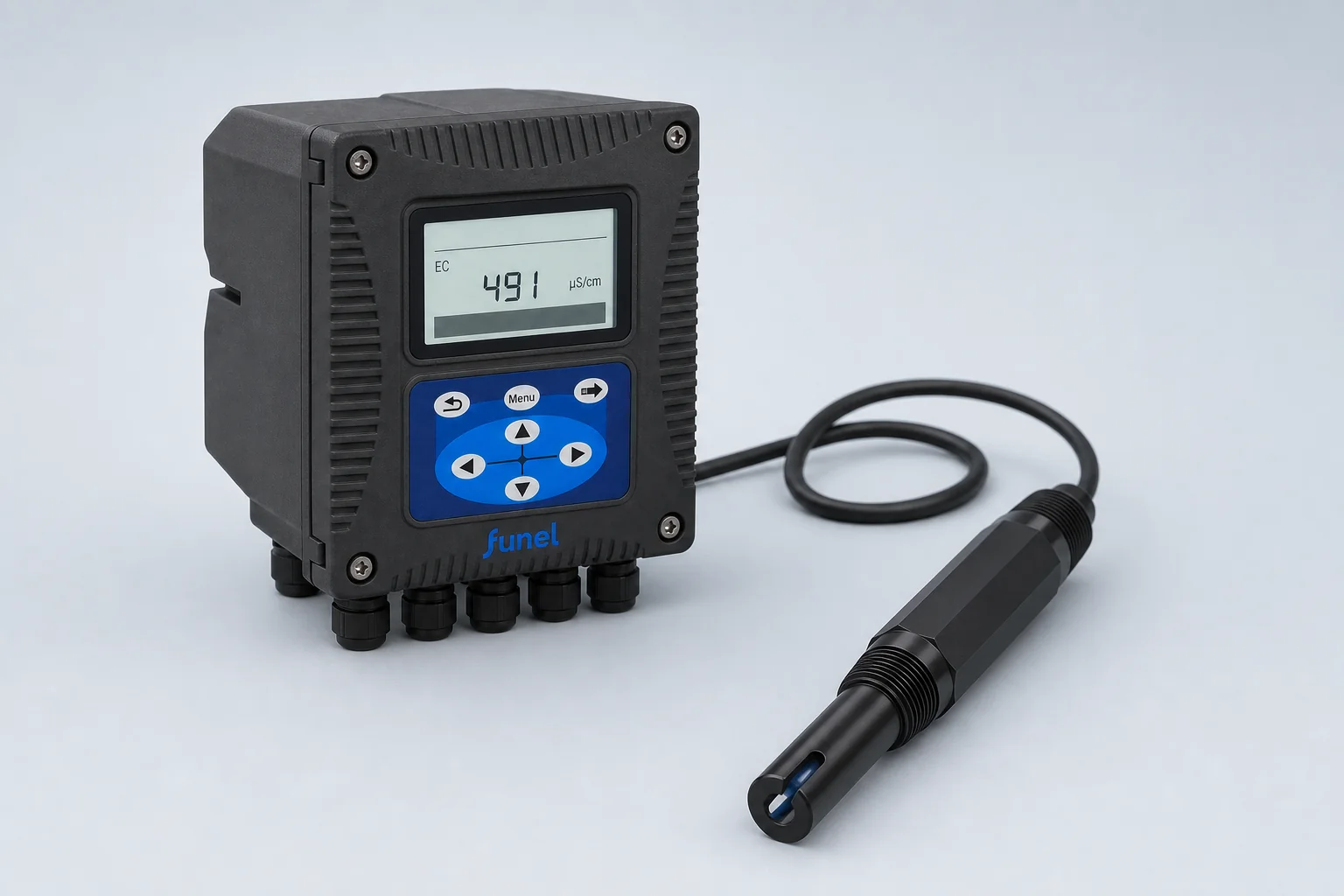
Online Conductivity Analyzer
View product↗
Portable Conductivity Analyzer
View product↗Selection & service
From selection to installation
Choose conductivity measurement by the actual operating range, cell construction and signal path. A complete analyzer and a digital sensor are different supply configurations.
Product literature
Download product brochures
Use the table for the exact model. The PEC-500B brochure distinguishes a 0–100°C temperature measuring range from a 0–45°C non-freezing electrode operating limit; do not use the measuring range as the service-temperature rating.
Contact FUNEL
Tell us what you need to measure.
We will respond with a recommended configuration, supporting documentation and quotation.